RF OPTICAL RECEIVER MODULE
ANALOGUE VERSION
Last updated: 29/01/2007 10:31
The analogue version, initially chosen for the transmission of all the timing signals, is now only used for 400MHz sinewave transmission. However, the modules were designed in the framework of the TTC upgrade, and the components were evaluated using a test board. The results are available here. The Version 1 of the modules were evaluated and the results are gathered in the TTC upgrade system test report.
VERSION 1 MODULES:

RF_Tx_A RF_Rx_A
EDMS EDA-01331-V1 EDMS EDA-01332-V1
DOCUMENTS:
First evaluation of the MITEQ link
Final test of the Version1 modules
EDMS Schematics and Layout of the RF_Tx_A: EDA-01331
EDMS Schematics and Layout of the RF_Rx_A: EDA-01332
RF_Rx_A User Manual
CVS repository fo RF_Rx_A graphical control panel (tcl&tk panels)
Money spent for the RF_Tx_A and for the RF_Rx_A: prototyping & components fully paid by AB/RF
Updated prices(5 boards, study deduced):
RF_Tx_A: ~18kCHF
RF_Rx_A:~15kCHF
FRONT PANELS:
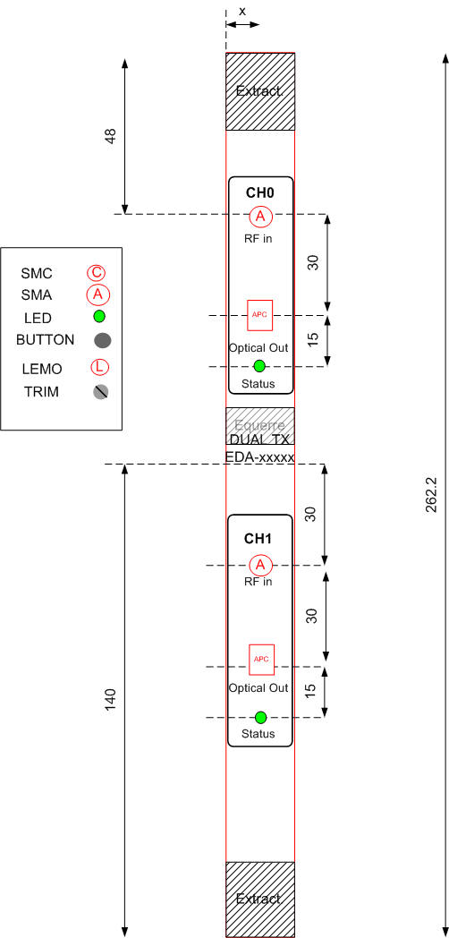
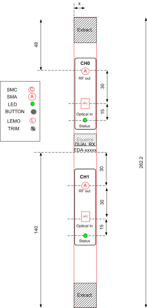
RF DUAL TRANSMITTER MODULE RF DUAL RECEIVER MODULE
PRINCIPLE:
Their principle is very simple, based on the following drawings:
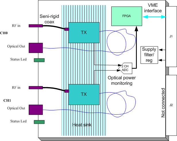
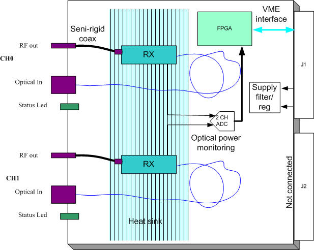
RF DUAL TRANSMITTER MODULE RF DUAL RECEIVER MODULE
COMPONENTS:
TX/RX:
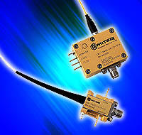
The transmitter and receiver modules are MITEQ receivers.
OTHERS:
ADC to convert the power monitoring level
VME INTERFACE to read the status of the optical components
HEATSINK for the optical components
FILTERS for the power supply of the optical components
TEST BOARD:
A module to evaluate the optical link was done and used for component evaluation.
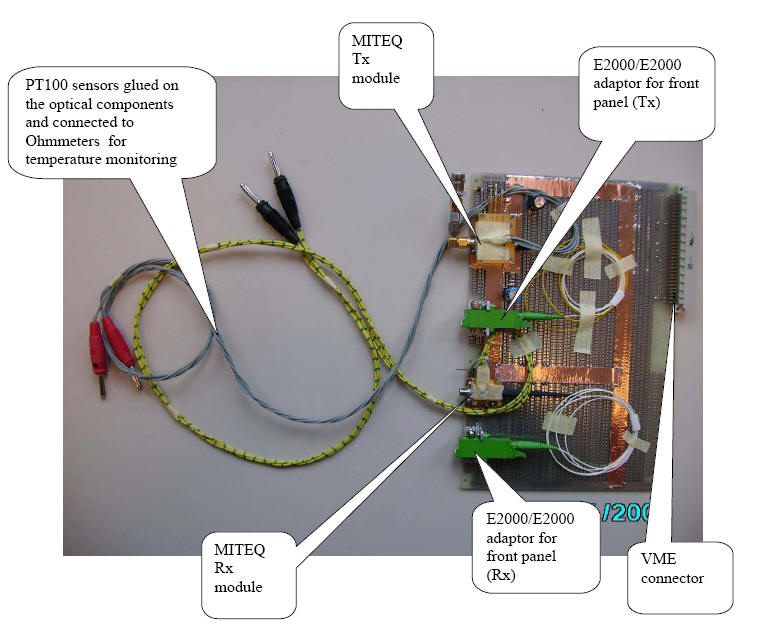
The temperature of the Rx and the Tx, without heatsink has been monitored with and without fans. The results are as follows:
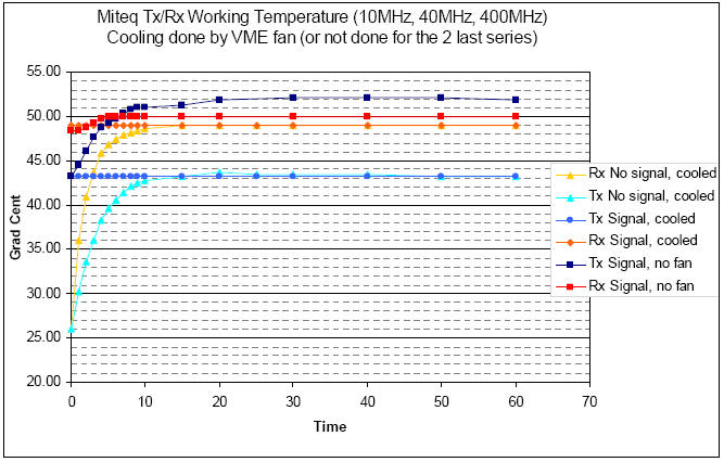
The Tx and Rx have not been stopped and cooled down between the 3 measurement sequences.
Last Updated by Sophie BARON on 29/01/2007 10:31